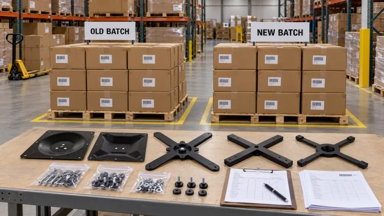
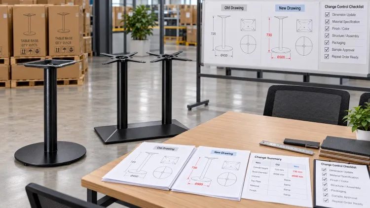
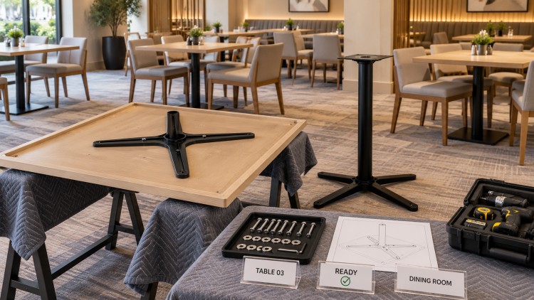
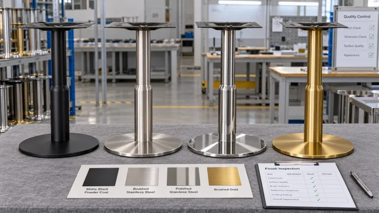
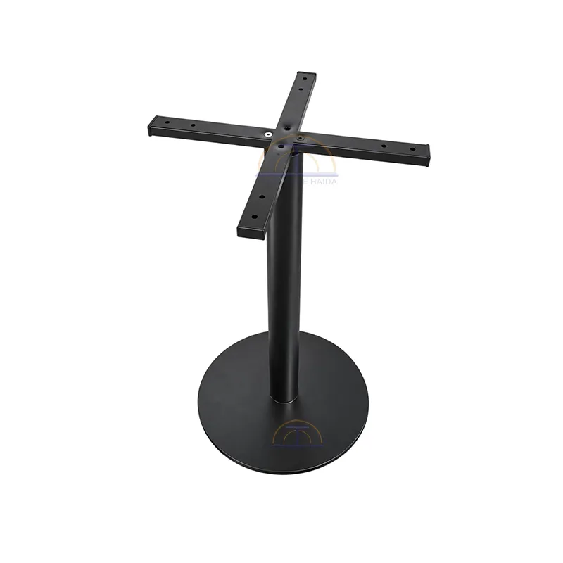
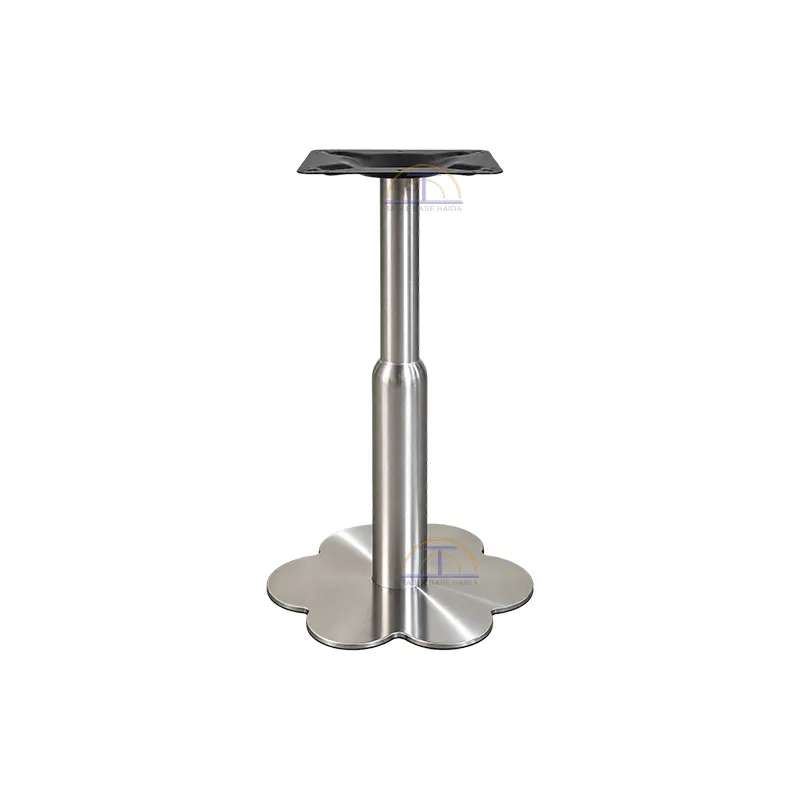
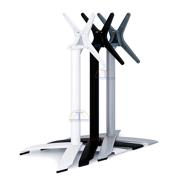
1. Why the Mounting Plate Deserves Its Own Specification
Commercial table buyers often spend more time discussing the visible floor base than the mounting plate hidden underneath the tabletop.
However, the mounting plate is the connection between the tabletop and the table base structure.
If the plate size, hole pattern, inserts or fasteners do not match, an otherwise suitable table base may create installation delays, additional drilling, adapter requirements or production rework.
For OEM tabletop factories, furniture dealers and project buyers, the mounting plate should therefore be treated as a controlled technical specification rather than a minor accessory.
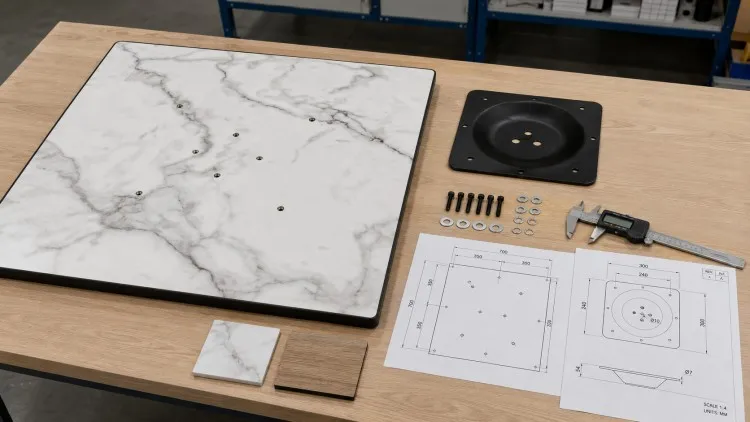
2. Use Consistent Terminology
Different suppliers may use different names for the same general component.
Common terms include:
- Top plate
- Mounting plate
- Spider plate
- Cross plate
- Mounting bracket
- Folding top
Before approving drawings, the buyer and supplier should confirm exactly which component each term refers to.
A specification that says only “450 mm top plate” is not complete unless the plate shape, hole pattern and fixing method are also understood.
3. Start With the Tabletop, Not the Base
The tabletop should be defined before the mounting plate is finalized.
The same table base may be used with several tabletop materials, but those materials may require different fixing systems.
Tabletop information should include:
- Shape
- Length and width
- Diameter
- Thickness
- Material
- Approximate weight
- Edge profile
- Underside reinforcement
- Existing inserts, if any
- Intended mounting method
This information determines whether the mounting plate can use direct screws, threaded inserts, mounting blocks or another fixing method.
4. Define the Complete Mounting System
The mounting plate should not be reviewed as an isolated metal part.
The complete mounting system includes the tabletop, inserts or fixing points, mounting plate, fasteners and table base column.
A mounting-system specification should identify:
- Tabletop material
- Tabletop thickness
- Mounting plate size
- Mounting plate shape
- Hole quantity
- Hole type
- Hole center distances
- Insert or screw type
- Fastener quantity
- Plate-to-column connection
- Drawing revision
Approving only one part of this chain can leave compatibility problems unresolved.
5. Record the Mounting Plate Dimensions
Mounting plate dimensions should be shown clearly on the technical drawing.
For a square or rectangular plate, record the overall length and width.
For a round plate, record the diameter.
For a cross-shaped or spider plate, the drawing should show the overall span and individual arm dimensions.
Useful dimensions include:
- Overall length
- Overall width
- Diameter
- Overall arm span
- Plate thickness
- Edge shape
- Column connection position
- Distance from plate edge to fixing holes
The product name alone should never replace these dimensions in an OEM drawing.
6. Dimension the Hole Pattern From Fixed References
A hole pattern should not be communicated only through a photograph.
The drawing should locate each important hole from clear reference lines or centerlines.
Common dimensions include:
- Horizontal center-to-center distance
- Vertical center-to-center distance
- Distance from centerline
- Distance from plate edge
- Bolt-circle diameter when applicable
- Hole diameter
- Slot length and width
- Number of holes
When several holes appear visually similar, numbering them on the drawing makes communication easier.
7. Distinguish Round Holes From Slotted Holes
Round holes and slots should not be treated as the same feature.
A round hole defines a more specific fixing position.
A slotted hole may provide limited installation adjustment, but the buyer should not assume that every slot is designed to compensate for a different tabletop hole pattern.
The drawing should show:
- Slot orientation
- Slot length
- Slot width
- Intended fastener position
- Whether adjustment is allowed
- Final tightening position
The supplier and tabletop factory should agree on the intended use of the slot before production.
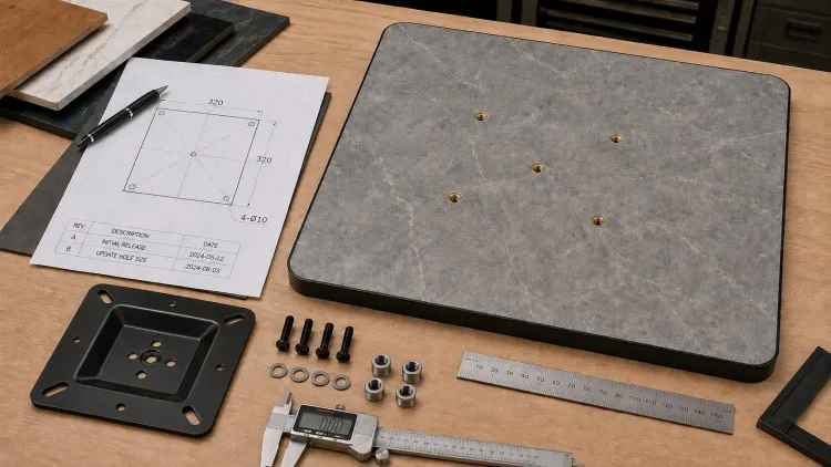
8. Match the Hole Pattern to Threaded Inserts
For OEM tabletops, threaded inserts can make assembly more repeatable when the insert pattern is controlled correctly.
However, the insert drawing and table base drawing must use the same coordinate references.
The insert specification should identify:
- Insert position
- Insert quantity
- Thread specification
- Installation depth
- Distance between inserts
- Distance from tabletop center
- Applicable screw or bolt
- Tabletop material around the insert
A mismatch between insert spacing and mounting plate holes can prevent assembly even when both components were manufactured correctly according to different drawings.
9. Match Fastener Length to the Tabletop Construction
Fasteners should be selected from the complete tabletop and mounting configuration.
A screw that works for a thick wood tabletop may not be suitable for a thinner panel or a tabletop using threaded inserts.
Confirm:
- Screw or bolt type
- Thread specification
- Diameter
- Length
- Washer requirement
- Nut requirement
- Insert engagement
- Quantity per table
- Tightening method
The tabletop manufacturer or qualified installer should confirm the fixing method for specialized tabletop materials.
10. Review the Mounting Plate as Part of the Load Path
The mounting plate does more than hold the tabletop in position.
It forms part of the load path between the tabletop, fasteners, column and floor base.
The mounting plate therefore needs to be reviewed together with tabletop size, weight, support position and overall table stability.
The Table Base Load Capacity Guide for Commercial Buyers provides a broader framework for reviewing the tabletop, base footprint, column, connection and final supported configuration rather than relying on one isolated load number.
For heavy or unusually large tabletops, the mounting connection should be reviewed as part of the complete table configuration.
11. Product Examples Show Why “Top Plate Size” Is Not Enough
Published product specifications demonstrate that commercial table bases can use different fixed or folding mounting plates.
The Brushed Gold Tulip Table Base HD-J226 currently lists a 450 mm top plate with dining and bar-height configurations. This information is useful for initial matching, but the buyer still needs the detailed hole drawing before locking an OEM tabletop insert pattern.
The Modern Tulip Stainless Steel Table Base HD-J156 also lists a 450 mm top plate and dining or bar-height options. Two products sharing a nominal 450 mm top plate should not automatically be assumed to use the same hole pattern.
The Industrial Folding Aluminum X-Base HD-J153 lists a 450 mm folding top plate. A folding top introduces additional mechanism geometry, so OEM tabletop positioning should consider not only the fixing holes but also the folding mechanism and its operating clearance.
The X-Base Adjustable Aluminum Lift Table Leg HD-J278 currently lists a 520 mm folding top plate. This provides another example of why plate size, mechanism and hole pattern should be treated as separate specification fields.
These products are examples of different mounting directions, not universal hole-pattern standards.
12. Request a Dimensioned Drawing Before Cutting the Tabletop
OEM tabletop production should not begin from a product photo or catalog screenshot.
The buyer should request a dimensioned mounting drawing from the table base supplier.
The drawing should ideally show:
- Top plate outline
- Overall dimensions
- Hole quantity
- Hole diameter
- Hole center distances
- Slot dimensions
- Plate thickness
- Column centerline
- Plate orientation
- Product model
- Drawing number
- Revision number
- Revision date
The tabletop factory should produce its corresponding insert or drilling drawing from the approved version.
13. Use One Coordinate System Across Both Drawings
Many hole-pattern mistakes are communication mistakes rather than machining mistakes.
The table base drawing and tabletop drawing should use a common reference system.
For example, both drawings can reference the tabletop centerline and indicate the mounting plate orientation.
Avoid situations where:
- One drawing dimensions from the plate edge and the other from the tabletop edge
- One drawing is viewed from above and the other from below without clarification
- The plate can be rotated but orientation is not controlled
- Symmetrical holes are assumed without dimensions
- The tabletop supplier uses an old drawing revision
A simple orientation arrow can prevent significant production errors.
14. Lock the Drawing Revision Before Mass Production
Mounting drawings can change during sampling.
A hole may move, a slot may be enlarged, the plate may change size or a fastener may be replaced.
Every technical drawing should therefore carry a revision identifier.
Revision control should include:
- Drawing number
- Revision number
- Revision date
- Description of change
- Person requesting the change
- Supplier confirmation
- Buyer approval
- Effective production date
Old versions should be withdrawn once the new revision is approved.
15. Approve the Mounting System During Sample Review
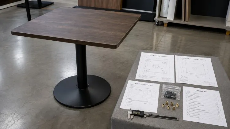
The sample stage is the best time to verify the complete tabletop-to-base connection.
The Commercial Table Base Sample Approval Checklist already emphasizes checking product dimensions, mounting details and the approved production reference before mass production.
The mounting sample should confirm:
- Correct top plate
- Correct hole pattern
- Correct tabletop inserts
- Correct fasteners
- Tabletop centered on the base
- No interference with the column or mechanism
- Full fastener engagement
- Final assembled stability
- Assembly sequence
One approved complete table is more useful than approving the tabletop and base separately without trial assembly.
16. Treat Folding Top Plates as a Separate Category
Folding table bases need additional mounting review because the top plate is part of a moving mechanism.
The buyer should not approve only the screw-hole layout.
Also review:
- Hinge position
- Locking mechanism
- Folding direction
- Release-handle clearance
- Tabletop edge clearance
- Reinforcement around fixing points
- Position when folded
- Interference with under-table components
The tabletop drawing should show enough information to avoid blocking the folding mechanism.
17. Control OEM Tabletop Drilling by SKU
Furniture factories producing several tabletop sizes should avoid using one generic drilling program for all table base models.
Each approved table-base-and-tabletop combination should have its own controlled SKU reference.
A useful combination code can connect:
- Tabletop SKU
- Table base model
- Top plate drawing
- Hole pattern revision
- Insert specification
- Fastener kit
- Finish
- Packaging version
This reduces the risk of a correct tabletop being drilled for the wrong base.
18. Inspect Hole Patterns During Production
Hole-pattern control should continue after sample approval.
Production inspection should verify the mounting plate and tabletop fixing points against the approved drawing.
Inspection can include:
- Overall top plate size
- Hole quantity
- Center-to-center spacing
- Hole diameter
- Slot size
- Plate flatness
- Plate orientation
- Insert positions
- Fastener fit test
- Trial tabletop assembly
Checking only one loose mounting plate may not identify a mismatch between the base and the actual production tabletop.
19. Pack the Correct Hardware With the Correct Mounting Version
Even a correct hole pattern can create installation problems if the wrong hardware is packed.
The hardware bag should match the approved tabletop and mounting-plate configuration.
The hardware record can include:
- Table base model
- Tabletop SKU
- Screw or bolt specification
- Quantity
- Washer quantity
- Nut quantity
- Allen key, if required
- Hardware bag code
- Drawing revision
- Assembly instruction reference
This is especially important when several mounting versions are packed in the same shipment.
20. Give Installers a Clear Assembly Reference
The final user should not have to reverse-engineer the hole pattern on site.
The shipment should provide a simple assembly reference showing the correct tabletop orientation, top plate position and fastener sequence.
Useful installation information can include:
- Product model
- Tabletop SKU
- Top plate drawing
- Hole-pattern diagram
- Fastener list
- Assembly sequence
- Tightening points
- Folding mechanism instructions when applicable
- Contact reference for missing hardware
Clear installation information reduces unnecessary drilling and on-site improvisation.
21. Common Mounting Plate and Hole Pattern Mistakes
Most mounting problems can be traced to incomplete specifications or uncontrolled revisions.
Common mistakes include:
- Specifying only the top plate size
- Assuming all 450 mm plates use the same holes
- Using photos instead of drawings
- Not dimensioning hole center distances
- Mixing top-view and bottom-view drawings
- Ignoring slot dimensions
- Choosing screws before confirming tabletop thickness
- Using a different insert pattern from the base drawing
- Updating the base drawing but not the tabletop drawing
- Packing hardware from an old revision
- Skipping complete sample assembly
- Using one drilling template across incompatible SKUs
A controlled drawing and sample process prevents most of these problems before mass production.
22. How Haida Supports OEM Mounting Coordination
Haida’s current commercial table base range includes fixed top plates, folding top mechanisms and different top plate sizes depending on the product model.
OEM buyers should send the tabletop material, dimensions, thickness, expected weight, insert plan and required table base model before locking the drilling pattern.
To review an OEM tabletop mounting plan, buyers can contact Haida for table base mounting coordination with the tabletop drawing and required table base model.
23. FAQ
Q1: Are table base mounting plate hole patterns universal?
No. Two mounting plates can have the same overall size but use different hole quantities, spacing, slot positions or fixing systems.
Q2: Is the top plate size enough to produce an OEM tabletop?
No. The tabletop factory should also receive the hole pattern, hole or slot dimensions, orientation, fastener information and drawing revision.
Q3: Should threaded inserts be installed before the table base sample arrives?
For a new combination, it is safer to confirm the approved mounting drawing and preferably complete one trial assembly before locking bulk insert positions.
Q4: Can slotted holes solve a mismatched tabletop hole pattern?
Sometimes a slot allows limited adjustment, but buyers should not assume it can compensate for any mismatch. The approved drawing should define the slot dimensions and intended adjustment range.
Q5: What should be checked before mass production?
Confirm the tabletop drawing, top plate dimensions, hole pattern, inserts, fasteners, orientation, drawing revision and one complete assembled sample.
24. Conclusion
A commercial table base mounting plate should be managed as a technical interface between two products rather than as a simple accessory.
OEM buyers should control the plate dimensions, hole pattern, tabletop inserts, fasteners, drawing orientation and revision before mass production.
The safest workflow is to use one approved drawing set for both the table base supplier and tabletop factory, then verify the complete configuration through trial assembly.
When mounting data is controlled at SKU level, future production, installation and repeat orders become easier to manage.